Introduction
Ontology alignment is the process of connecting system models (like those created with SysML) to formal ontology classes, enabling seamless integration between modeling tools and semantic technologies. It bridges the gap between traditional engineering modeling and machine-readable knowledge representation.
|
Think of ontology alignment as creating a "dictionary" that translates between the language of your modeling tool (e.g., SysML) and the language of semantic technologies (e.g., OWL ontologies). |
Overview
Ontology alignment is a core technique in the Digital Engineering Framework for Integration and Interoperability (DEFII) that enables the integration of different modeling approaches. It’s implemented through the Armaments Interoperability and Integration Framework (IoIF), which connects SysML models to ontologies to create a shared semantic foundation for digital engineering.
The alignment process uses stereotypes in SysML v1 or metadata in SysML v2 to tag model elements with corresponding ontology classes, allowing for automated reasoning, better data integration, and more effective decision-making across different domains.
|
Ontology alignment is not just about mapping terms - it’s about creating a consistent, machine-readable representation of domain knowledge that can be used across different tools and teams. |
Position in Knowledge Hierarchy
Broader concepts: - Part II (is-a)
Narrower concepts: - Stereotypes (is-a)
Details
The Alignment Process
Ontology alignment involves the following key steps:
-
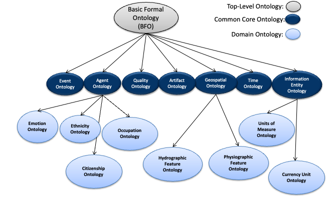
Define the domain ontology: Create or select an ontology that represents the domain concepts (e.g., using BFO as a top-level ontology and CCO as a mid-level ontology)
-
Identify model elements: Determine which elements in the SysML model need to be aligned with ontology classes
-
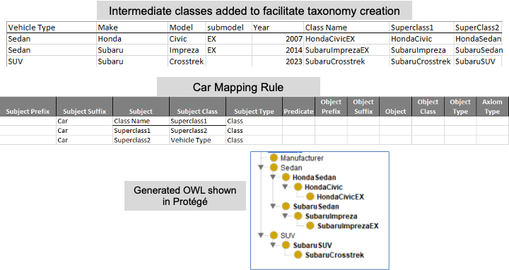
Map elements to ontology classes: Use stereotypes or metadata to connect SysML elements to ontology classes
-
Validate the alignment: Ensure the mapping is consistent and complete
|
The alignment process must follow ontology alignment principles to ensure interoperability and consistency across different models and tools. |
Key Concepts
Concept |
Description |
Ontology |
A formal representation of a set of concepts within a domain and the relationships between those concepts |
SysML Stereotypes |
Custom extensions to SysML that allow for adding metadata to model elements (SysML v1) |
Metadata |
The replacement for stereotypes in SysML v2, allowing for adding metadata to model elements |
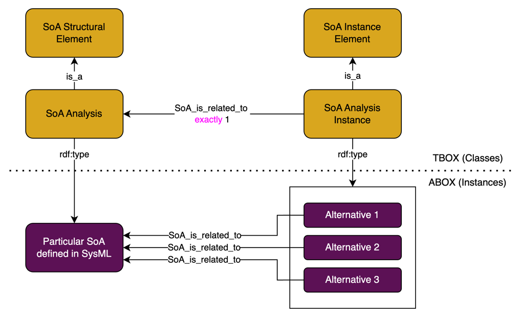
Triplestore |
A specialized database for storing and querying RDF data (subject-predicate-object triples) |
IoIF |
Armaments Interoperability and Integration Framework, which implements ontology alignment |
|
Avoid creating ontology classes that duplicate existing terms or concepts. This can lead to inconsistencies and reduce interoperability. |
Alignment Principles
When aligning ontologies with digital engineering models, the following principles should be followed:
-
Use clear and descriptive names: For SysML blocks, properties, and OWL classes to ensure readability and maintainability
-
Follow ontology alignment principles: Refer back to the principles discussed in Section 5 of the context
-
Reuse existing ontologies: Where possible, use existing ontologies like BFO or CCO rather than creating new ones
-
Ensure consistency: The concepts, relationships, and functionalities represented in both the SysML model and the OWL ontology should be consistent and complementary
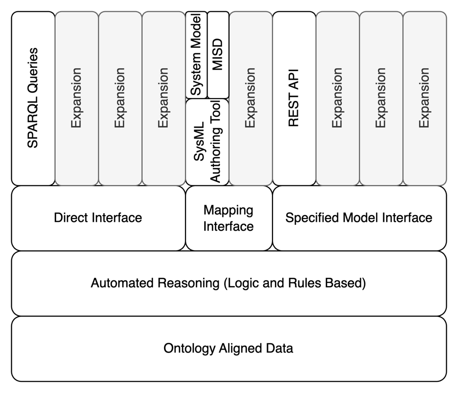
|
The DEFII framework specifies three categories of interfaces for ontology alignment: Direct Interface, Mapping Interface, and Specified Model Interface. |
Practical applications and examples
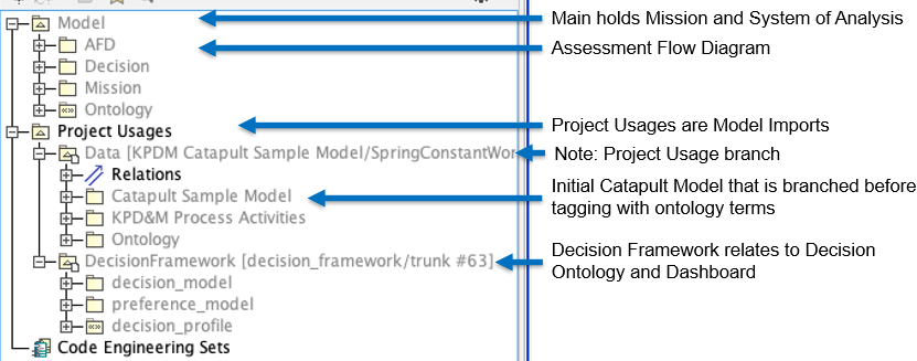
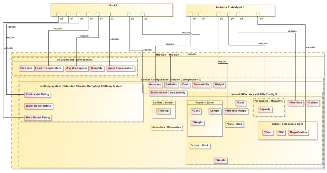
Catapult Model Example
The catapult example demonstrates how to align a SysML model with an ontology:
-
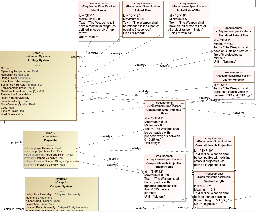
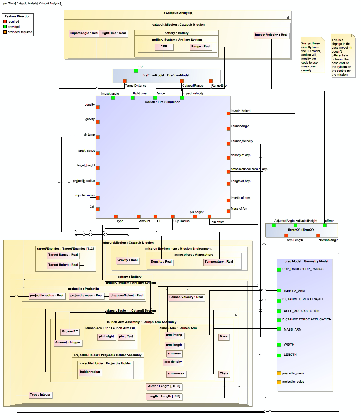
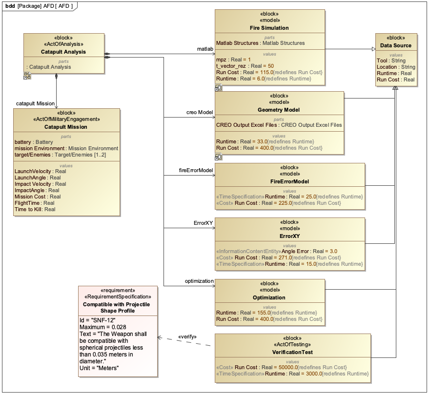
Start with an existing SysML model of a catapult system
-
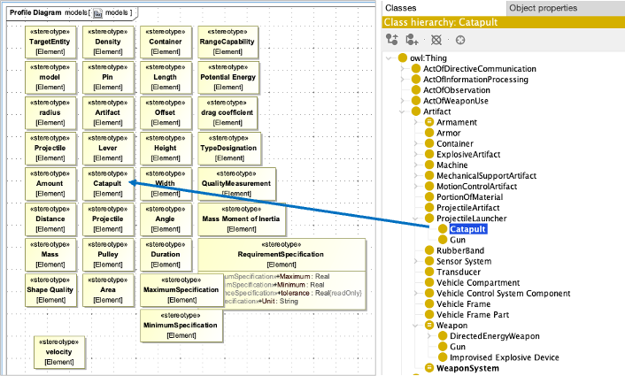
Create an ontology using Protégé that defines classes like Catapult, Projectile, LaunchMechanism, etc.
-
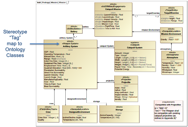
Add stereotypes to the SysML model to connect model elements to ontology classes
-
Validate the alignment to ensure consistency between the model and ontology
|
The catapult example in the context shows how to extend the model with a "safety mechanism" feature by adding a new block to the SysML model and corresponding class to the ontology. |
Step-by-Step Alignment Process
Here’s a step-by-step guide to aligning a SysML model with an ontology:
-
Prepare the ontology:
-
Open Protégé and create a new ontology
-
Import the Basic Formal Ontology (BFO) as a top-level ontology
-
Add domain-specific classes (e.g., Catapult, LaunchMechanism)
-
-
Define the ontology classes:
= Example OWL class definition
Class: Catapult
  SubClassOf: PhysicalObject
  EquivalentTo: (hasPart some LaunchMechanism) and (hasPart some Projectile)
-
Create a SysML model:
-
Open your SysML modeling tool (e.g., MagicDraw, Cameo Systems Modeler)
-
Create a Block Definition Diagram (BDD) for the catapult system
-
-
Add stereotypes to SysML elements:
-
Right-click on a SysML block (e.g., "Catapult")
-
Add a stereotype that maps to the ontology class (e.g.,
[Catapult]) -
Repeat for other relevant elements (e.g., "LaunchMechanism" block with
[LaunchMechanism]stereotype)
-
-
Validate the alignment:
-
Use the IoIF workflow to check that the SysML model elements are correctly mapped to the ontology
-
Run reasoners to verify consistency
-
|
The key to successful ontology alignment is ensuring that the names used in the SysML model match the ontology classes as closely as possible, with clear and descriptive naming conventions. |
References
Protégé Ontology Editor
SysML v2 Documentation
Basic Formal Ontology (BFO)
Common Core Ontologies (CCO)
OWL 2 Web Ontology Language
RDF Concepts
Dunbar, D., et al. (2023). Driving Digital Engineering Integration and Interoperability Through Semantic Integration of Models with Ontologies, Systems Engineering Journal
Knowledge Graph
Associated Diagrams